- an empirical method, introduced by Thomas Stevens in Moudon.
- method suggested by Henri Gallarette, instrument maker in Marseille.
- method developed by Jean Louis Mouton and René Périnelli.
First we shall give a description of valve and case (Ill. 1, 3rd valve).
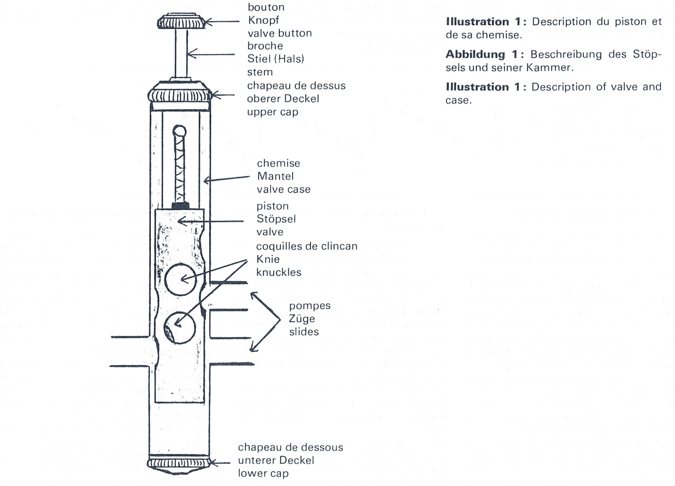
Illustration 1
1st Method
Presented by Thomas Stevens, based on the various harmonic characteristics of the instrument.
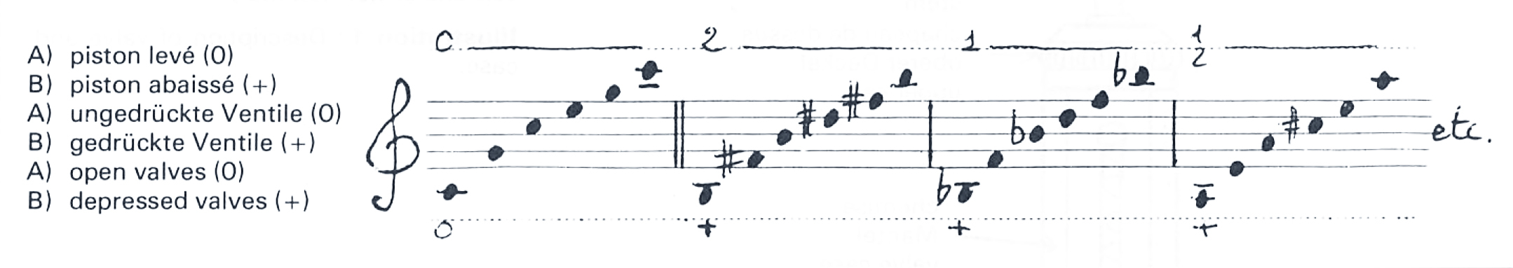
Illustration 2
A) Adjustment with open valves (O)
The air which vibrates in the instrument becomes noticeable at the level of the 3rd valve, after having passed through the mouthpipe. Therefore the 3rd valve must be adjusted first: the upper cap (Ill. 2) is screwed on and the valve piston more or less pulled up from within the case. Here can be ascertained whether the inner felt ring is too thick or has become too thin (Ill. 3).
The thicker the inner felt ring under the upper cap is, the further down can the piston be depressed into its case. The thinner the inner felt ring is, the higher the piston can be pulled.

Illustration 3
For the final adjustment of the piston felt rings of various thicknesses are introduced according to the correct height (Ill. 3): if the piston valve can be depressed too deeply then the felt or cork ring must be thinner, if it can’t be depressed enough then the felt or cork ring must be made thicker.
Differences in tone colour, response and intervallic relationships can be ascertained if the natural harmonics of the instrument are played without valves:
Then the first valve is adjusted, because the sound produced here receives the quality which is then realized in the bell. The procedure is the same as previously described: the upper valve cap is screwed on lower or higher while the natural harmonics are played with open valves.
Finally, if the difference is not sufficient then the 2nd valve is likewise adjusted.
B) Adjustment with depressed valves (+):
The length of movement of the piston is determined by the length of the valve stem: when the piston is depressed the following is ascertained: the longer the stem, the further the piston can be lowered into its case. The shorter the stem, the less the piston can be depressed.
For the correct adjustment of the length of stem the button is more or less screwed off (Ill. 4), then rings of various thickness are inserted (Ill. 5). Here also it is a question of achieving absolute correspondence between the knuckles of the slides and the piston holes. This time a visual estimate is sufficient since it is easy to check if the 2nd valve holes correspond. According to the instrument this method can also be applied to the 3rd and 4th valve.
Differences in tone colour and response can also be ascertained here, when the harmonics with various fingerings are played in the following manner:
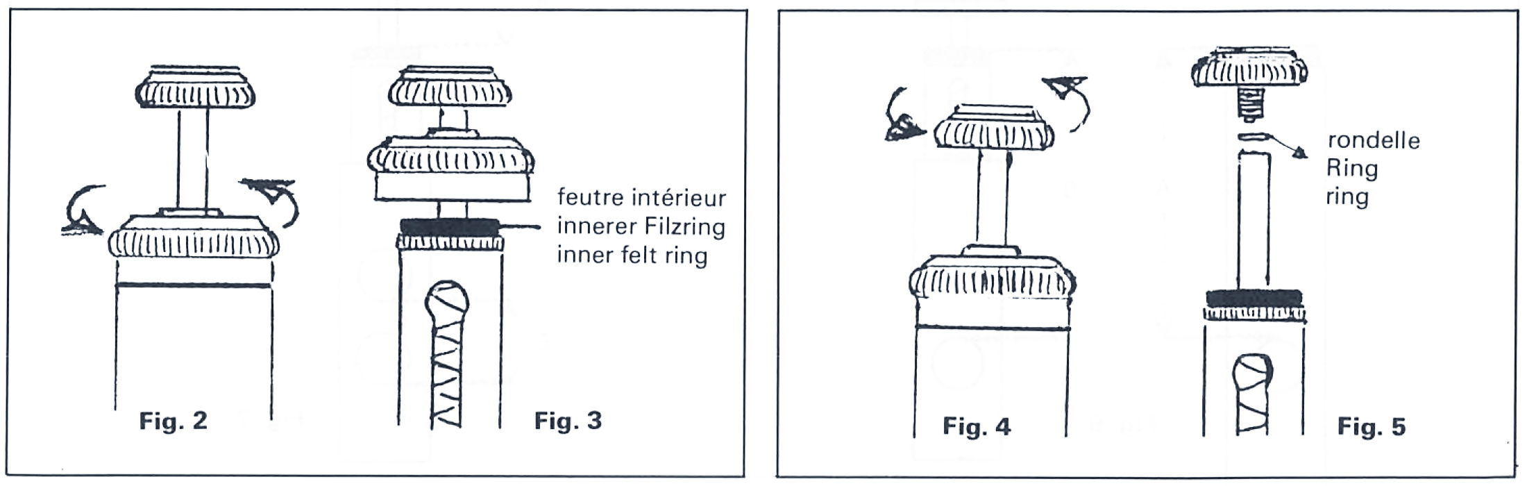
Illustration 4

Illustration 5
Finally
Of course any differences depend on the quality and the state of the instrument involved and can therefore be insignificant or considerable. This method allows for a pretty good adjustment after a certain amount of experience without any particular material (except the rings of various thickness).
Second method
Suggested by Henri Gallarette, instrument maker in Marseille. Comparative method, which gives more precision.
A) Adjustment with open valve (O)
A must be the same as B. In this way the holes in the piston and the valve case correspond exactly (Ill. 6, 3rd valve).
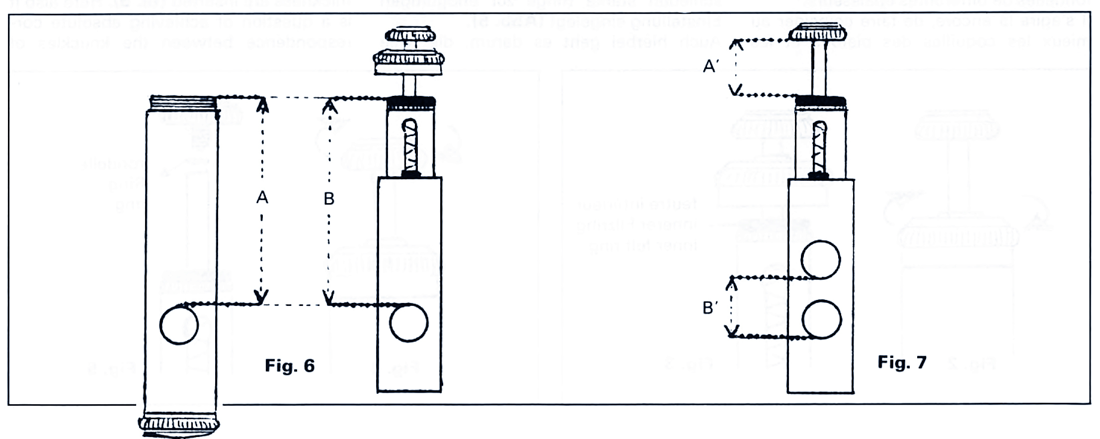
Illustration 6, Figure 7
B) Adjustment with depressed valve (+)
A’ must be the same as B’ (reason same as above) (Ill. 7).
Naturally the holes which correspond must be chosen. In order to measure the various lengths a slide rule is necessary. This method is simple and exact, if the measurements are carried out with open valves (A); there are however difficulties when measuring the stem with depressed valves (B) unless a slide rule with depth gauge is at hand.
NB: The lengths D and C of the upper cap must be identical if this method is used; as in the following illustration reversed upper cap (Ill. 8) or according to the model of the trumpet the screw thread of the valve case is the same as the valve cap (Ill. 9). Normally it is D > C which falsifies the final result.
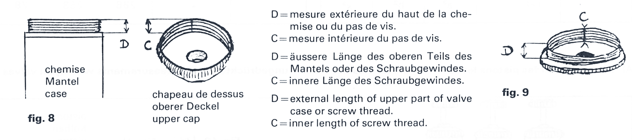
Figure 8 and 9
Third method
By Jean Louis Mouton and René Périnelli which offers the possibility of achieving an accuracy of 1/10 mm, i.e. a guarantee of extreme precision.
In order to apply this method a small piece of apparatus is necessary for measuring the lengths A and B (see following illustrations), (if you have any difficulty in making this, we can advise you), and a 1/10 mm slide/depth rule and possibly a calculator.
The precision with which the following measurements are taken makes for a perfect adjustment of the valves. In addition, as in the other two methods felt or cork rings of various thickness are required for the final adjustment.
The basic idea of our method is quite simple. Here is one example. This table helps in working out the various results:
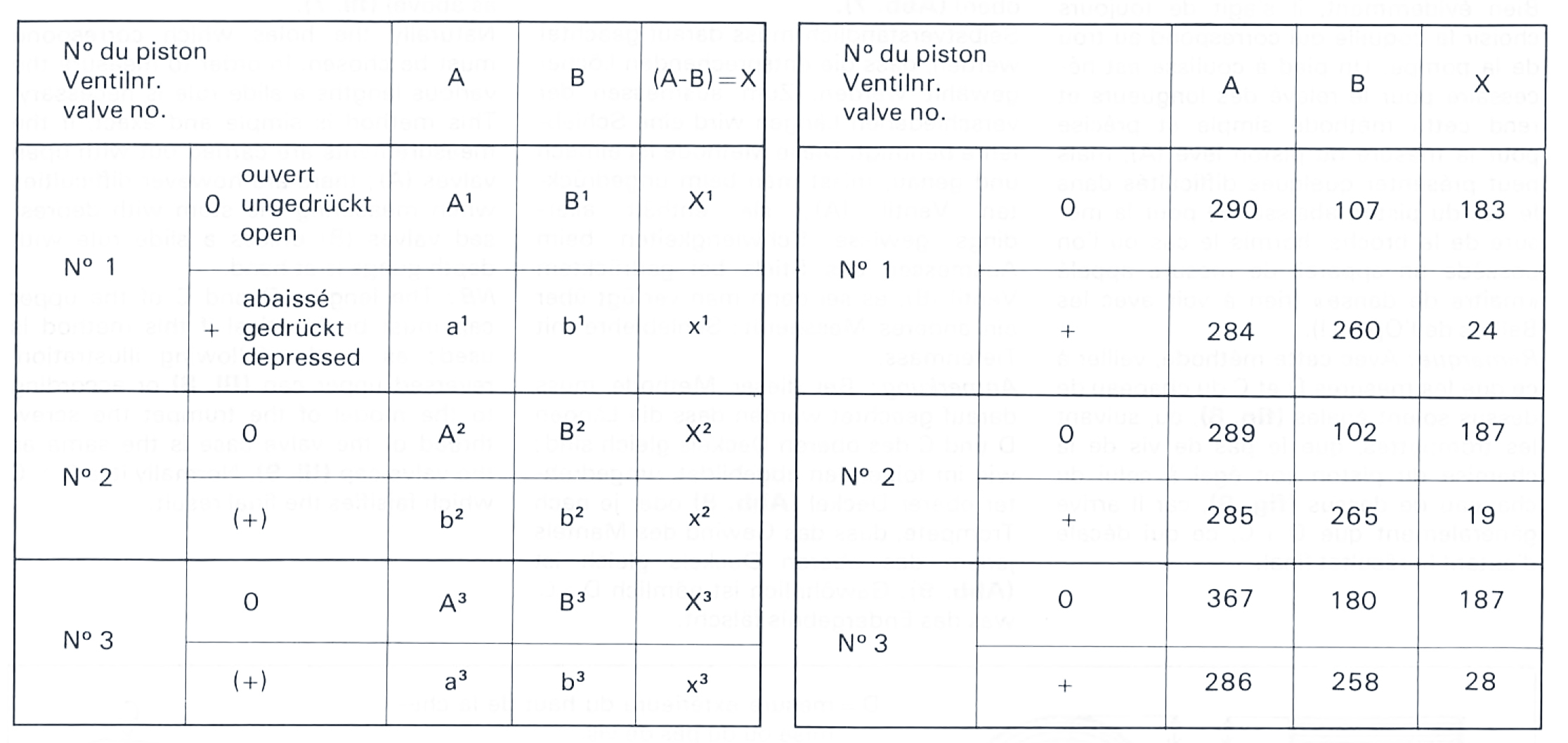
Example of measurements of one instrument. Unit: 1/10 mm.
A) Measurements with open valves
- Measure lengths A1, A2, A3 along the case walls with the apparatus (Ill. 10). Check with slide rule.
- Measure corresponding lengths B1, B2, B3 on the piston (Ill. 11). Check with slide rule also.
- Enter these lengths in the table and work out X: A1— B1 = X1 / A2— B2 = X2 / A3 —B3 = X3 (Ill. 12).
After each piston has been replaced in its case, the X values are set on the slide rule. Remove lower cap and introduce corresponding length under each piston with the depth gauge (Ill. 12). Check whether this length corresponds to the position of the piston: If the gauge doesn’t touch the piston (if it is too short), a thicker felt ring must be inserted: the piston can be pushed further down (Ill. 13). If the depth gauge pushes against the piston (if it is too long), a thinner felt ring must be inserted: the piston is pulled up (Ill. 14).
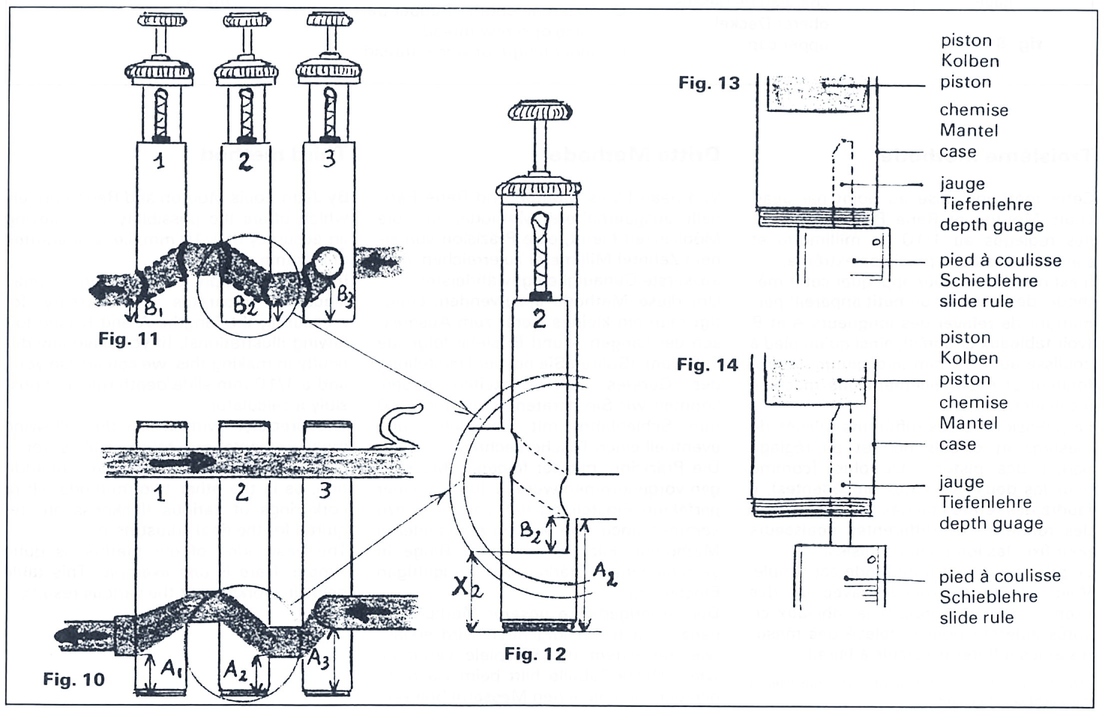
Figures 10 to 14
B) Measuring with depressed valves
As with open valves:
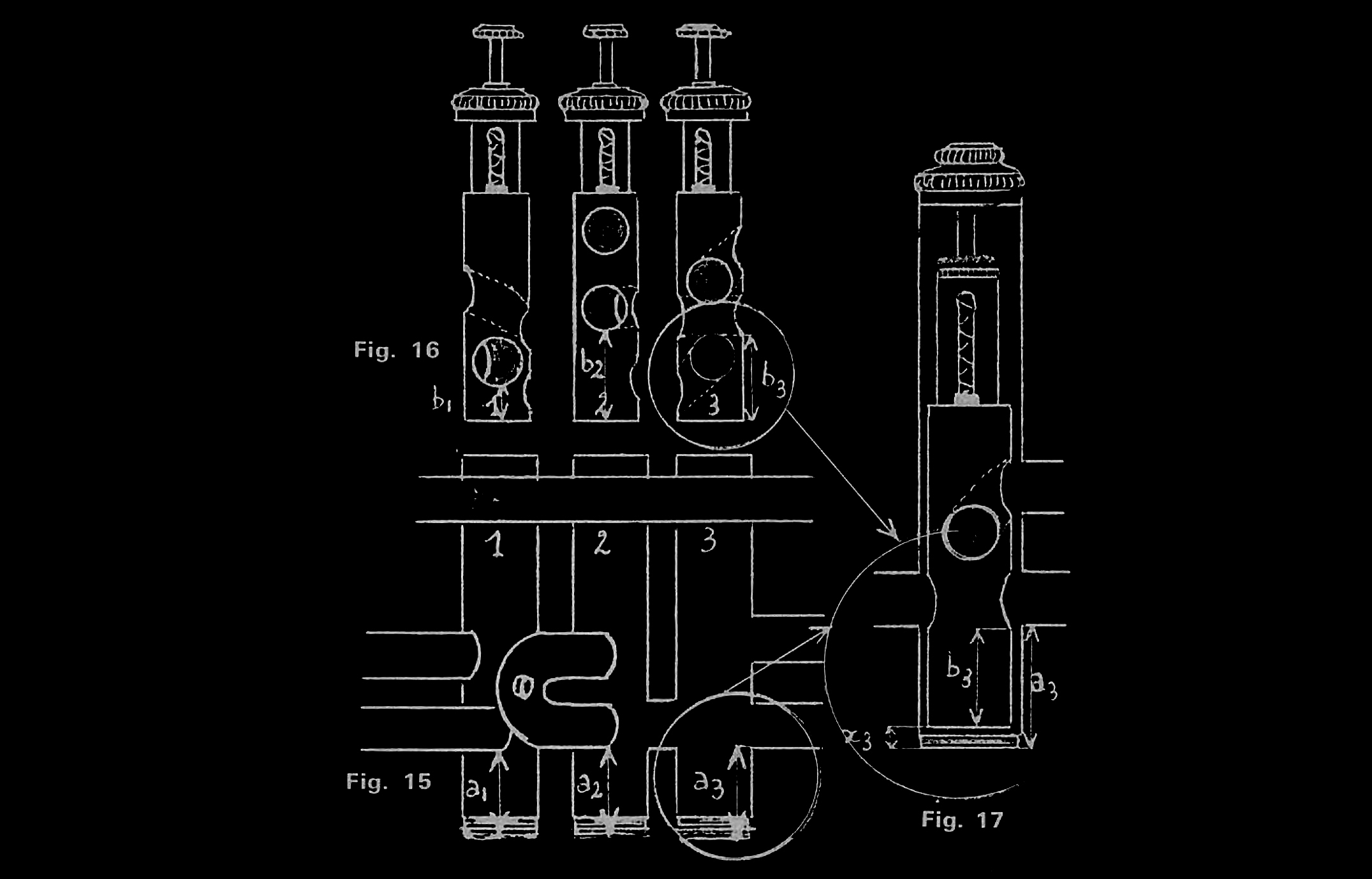
- Measure lengths a1, a2, a3 along case walls with slide rule (Ill. 15).
- Measure corresponding lengths b1, b2, b3 on the piston (Ill. 16).
- Work out X values: a1—b1=x1 / a2—b2=x2 / a3—b3=x3 (Ill. 17).
As above replace each piston into its case and transfer x values with depth gauge (with depressed valves!) (Ill. 17).
Figures 15 to 17
NB: In the case of depressed valves the x values are minimal. Therefore a maximum of precision is necessary when measuring and calculating.
General remark
There is the choice of two positions when measuring: entry or exit of the air column through the valve. The piston hole must always correspond to the correct knuckle in the valve. According to the make of instrument a certain amount of play sideways between the piston and the valve case will be found — but hardly anything can be done about this.
Conclusion
We hope that our enlightenment on this subject will be of future use to others. Our work will not have been in vain. Further research is certainly possible. In this case we would have reached our goal. We are at the disposal of anyone who would like to find out more: René Périnelli, “L’Horizon” — Château Sec, 10, bd de la Gaye, F-13009 Marseille.